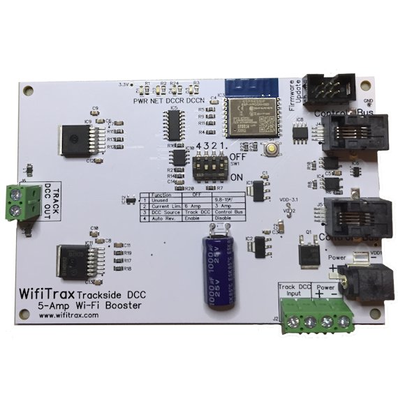
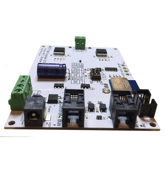
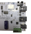
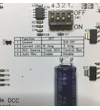
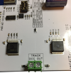
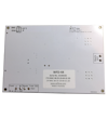
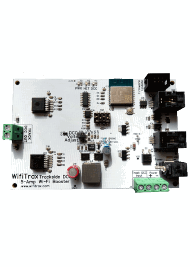
WFD-44 5A Wi-Fi/DCC Trackside Booster
Check out these related products
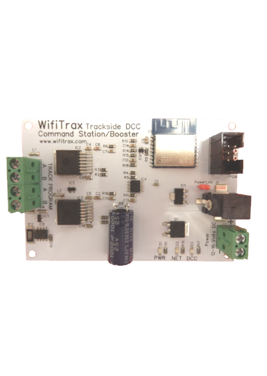
WFD-27 5A Wi-Fi/DCC Command Station/Booster
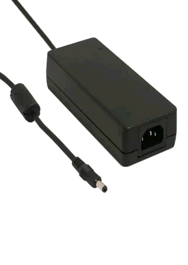
PA15-60-1 Power Adapter 15V 6.0A
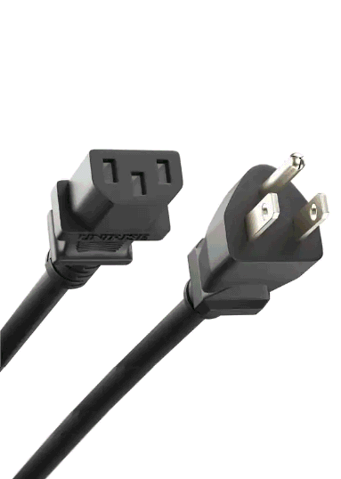
PC10-50-US-1 US 5-Foot Power Cord 10A
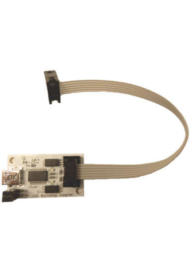
FWA-20 Firmware Upgrade Module
WFD-44 5A Wi-Fi/DCC Booster with Auto Reverse and Fixed Track Voltage
Available Now
The WFD-44 adds power districting to your DCC system.
You can install this Wi-Fi/DCC Booster on your layout to provide bipolar DCC encoded power to your track or layout accessories.
The DCC peak to peak output voltage is fixed and dependent on your power supply input and auto reverses as locos go over the gaps to keep the polarity
in adjacent power districts the same.
You can connect any DCC signal to its input that is compatible with the NMRA DCC standard either using the Control Bus or using the Track DCC Inputs.
A good choice is the WFD-27 Wi-Fi/DCC Command Station/Booster or the WFD-28 Command Station. You can also use the WFD-44 with any other NMRA compatible DCC Command Station simply as an auto-reversing 5A booster.
You can chain these boosters to set up multi-power district, DCC layouts.
WFD-44 5A Wi-Fi/DCC Trackside 5 amp Booster
This module is a DCC Booster and can be easily installed on any scale model railroad to provide Wi-Fi control of DCC Locomotives and Accessories. It is compatible with NMRA compliant command stations and decoders.
The WFD-44 requires a DCC input from a command station. This can be either bi-polar DCC as would be supplied to your track or it can be in the NMRA Control Bus balanced RS-485 format. The WFD-44 provides a Control Bus output that may be connected to other WFD-44 to provide mulitple power districts.
The DCC output voltage to the track is fixed and its peak to peak value will be slightly lower than the power supply voltage. Normally you would use a 15V Power Adapter which would give about 14V DCC Signal. For N Gauge, you should use a lower voltage power adapter and for O gauge or above, an 18V adapter would perhaps be better (check your DCC decoder documentation). If you need a higher voltage than this, check out the WFD-46.
The WFD-44 also provides its own web pages accessible via Wi-Fi on which you can monitor the status, including the approximate current drawn, as well as manually set the direction of the output.
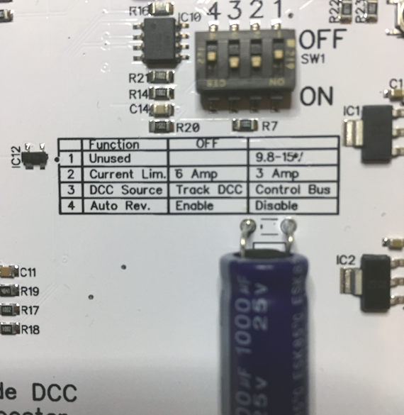
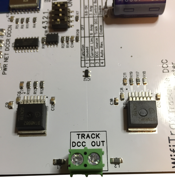
Main Track DCC Output is provided. Over-current shutdown protects both the booster and your equipment and can be set at 3A or 5A
WFD-44 5A Wi-Fi/DCC Trackside Command Station/Booster
Preliminary Specification - Subject to change until product is released for sale.
Dimensions
Length: 120mm (4.72") Width: 80mm (3.15") Maximum Height: 14mm (0.55")
Functions and Modes of Operation
Installs on your layout to provide direct Wi-Fi control and supply of Bipolar DCC to main track or portions of main track defined as power districts.
Output Ratings
Maximum Continuous Current Main Track: 5.0 Amp.
Power Supply Options
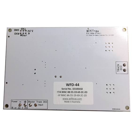
(1) 12 to 18 Volts DC independent power, wired to screw teminals on unit. This unit does not operate using AC. Input must be connected with correct polarity
but module is protected against power reversal.
(3) Plug-in 15V mains adapter connected directly to unit - available separately.
Mounting
Four M3 mounting holes for use with screws, nuts and spacers, or suitable wood screws with spacers. Mounting kit provided.
Connections
One pair of screw terminal outputs to connect bipolar DCC power output to main track.
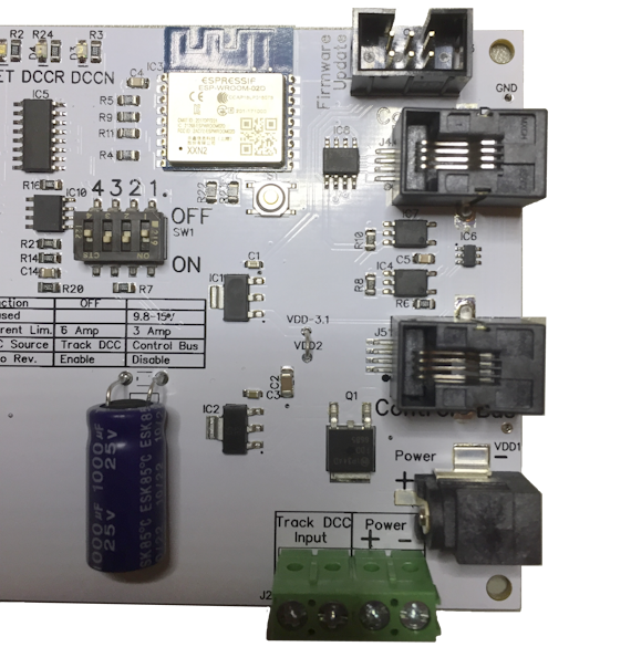
One pair of screw terminal inputs to connect optional bipolar DCC power as input (opto-isolated on module).
Two RJ10 sockets to be used as input or output for balanced RS-485 DCC Control Bus from Command Station. These act as output when module is set to use track DCC as input
Two screw terminal connections for DC power input, (acts as power output when barrel connector used).
Barrel connector for alternative 15V - 22V DC Mains Adapter (Sold Separately).
LED Indicators
Red LED indcates that power is present at the unit.
Green LED flashes when a hand-held device communicates via Wi-Fi. Lit constantly when on home network.
Blue LED indicates DCC is received by the unit and is delivered to main track. Blue LED flashes when overload shutdown occurs.
Yellow LED that lights instead of the Blue LED when power is reversed.
Mains Adapter Details
The power adapter must supply between 12 and 18 Volts DC (15V recommended for HO) with a Barrel Plug (2.5mm I.D. x 5.5mm O.D. x 9.5mm). The center pin must be positive. A recommended power adaptor is available from WifiTrax: http://www.wifitrax.com/products/product-PA15-43-1-detail.html
Protection
The module shuts down automatically when the current on its track outputs exceeds approximately 6A or 3A as selected, or when a short of the main track occurs. Power is restored automatically when the short is removed.
Protection is provided against accidental reversal of the power input to the module. Note that your Power Adapter may shut down before this module. Also the resistance (impedance) of the wires to your track
may limit the short circuit current when the module is set to 6A.

