WFD-29 Wi-Fi/DCC Trackside Command Station/Booster

Check out these related products
WFD-46 Wi-Fi/DCC 5A Booster with Auto-Reverse
WFD-44 Wi-Fi/DCC 5A Booster with Fixed Voltage and Auto-Reverse
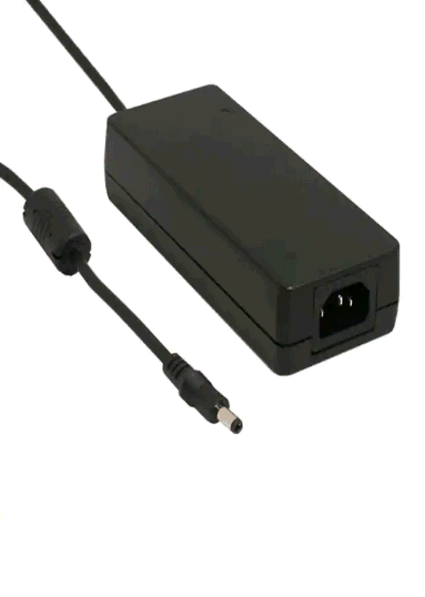
PA15-60-1 Power Adapter 15V 6.0A
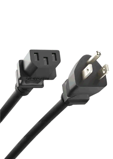
PC10-50-US-1 US 5-Foot Power Cord 10A
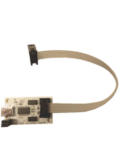
FWA-20 Firmware Upgrade Module
WFD-29 5 Amp Wi-Fi DCC Command Station/Booster with NCE Cab Bus Support
Available now
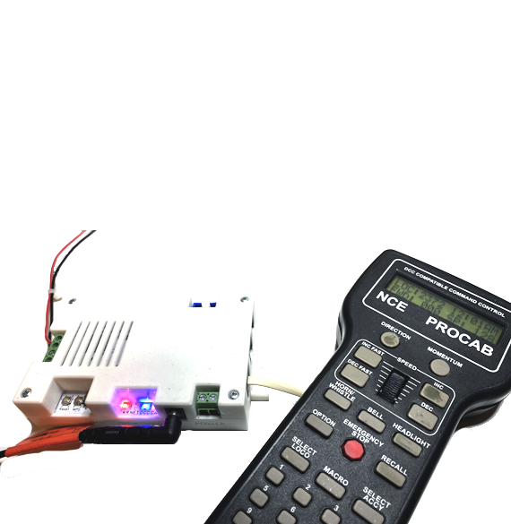
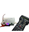
The WFD-29 along with a phone, tablet or NCE Pro Cab is a complete Wi-Fi DCC solution!
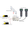
You can install this Wi-Fi/DCC Command Station on your layout to provide 5A rated DCC to your track. You can also add Boosters to its Control Bus for multiple Power Districts.
The WFD-29 provides NCE Cab Bus connectors. You can connect any NCE Cab devices to these such as a Pro Cabs or Power Cabs (The Power Cabs will act as Pro Cabs), NCE USB Adapter, or Wifitrax WFD-30 or 31.
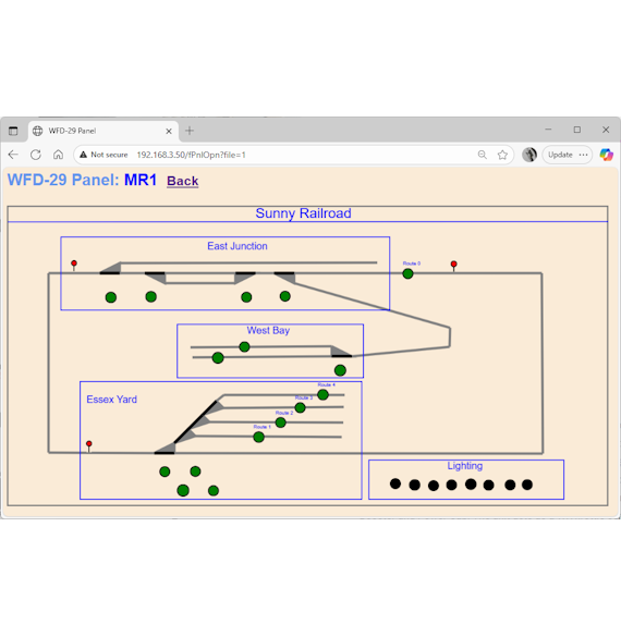
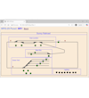
You can control trains from your tablet or smart phone running one of the WiThrottle Apps such as Engine Driver for Android, WiThrottle for Apple or use the TCS UWT-100 or UWT-50. Commands will be passed on to a set of locomotives or accessories equipped with DCC decoders. Each locomotive will be addressed separately and be under independent control. The WFD-29 module may receive commands from more than one tablet, addressing the same or different locomotives. A roster of up to 100 locomotives with Function Labelling, or 200 accessories can be stored in the WFD-29 so that you can select the locomotive you want to drive from the WiThrottle app. The WFD-29 also provides its own in-built Web Throttle that can be used to drive trains from any phone, table or computer with a browser such as Safari, Edge or Chrome.You can also build panels with track plans including turnouts, lights, signals, track etc. and control DCC accessories from there.
The WFD-29 also supports a programming track so that you can read and write DCC configuration variables in DCC Service Mode. You can also program operational mode addresses and other configuration variables on the main track.
Known issues and workarounds.WFD-29 5 Amp Wi-Fi DCC Command Station/Booster with NCE Cab Bus
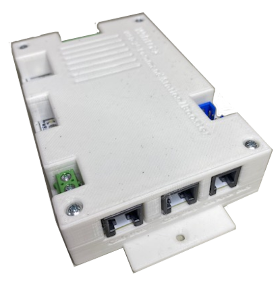
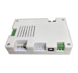
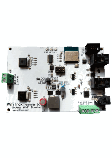
This module is a complete 5A DCC Command Station/Booster and can be easily installed on any scale model railroad to provide Tethered or Wi-Fi control of DCC Locomotives and Accessories. Unlike many of our board level products, this one comes in a plastic box to avoid disasters such as dropping your module onto track.
You can drive your trains from your tablet or smart phone running one of the WiThrottle Apps such as Engine Driver for Android, WiThrottle for Apple or the TCS UWT-100/50.
This module also supports an NCE Cab Bus, as a Cab Bus Master, so you can plug in your existing NCE Pro Cab, NCE Power Cab (which will act as a Pro Cab) and some other NCE Cab Bus client products such as the USB Adapter connected to a computer running JMRI. Connection to JMRI allows you to program locomotives from your JMRI configuration. So you can drive trains using your existing plug-in NCE Cabs. You can also connect Wifitrax adapters such as WFD-30 and WFD-31, which will allow more Wi-Fi phone or tablet cabs to connect.
You can use the in-built 5 Amp DC Booster to connect to your track and also connect one or more DCC Boosters to its Control Bus output to support multiple Power Districts
You can enter up to 100 locomotives in the module's roster with function labelling, then select a loco from the roster to drive. Alternatively you can just enter a DCC address of an unrostered loco.
For example, you might have a collection of locomotives HO or N scale that you have bought with DCC deccoders already installed or you might have installed some yourself. You can mount this module on your layout and connect its Control Bus output to your DCC Boosters. You can then enter all your locomotives (up to 100) into the roster contained within the module. The WFD-29 module will behave as a DCC command station compatible with any NMRA DCC Booster.
Up to 200 named accessories may be entered and selected via the phone app or you can simply enter the accessory address. You can build Panels with track, turnouts, lamps signals etc. in a schematic track plan. You can use these to operate DCC accessories on your layout. You can also create up to 50 Routes each with as many as 10 turnouts and operate these from buttons on your panels or from your phone apps or TCS UWT-100/50.
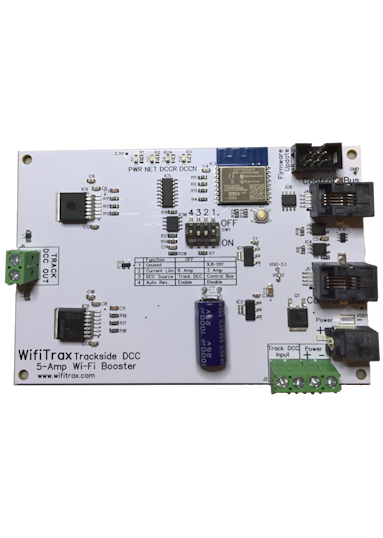
If you experience Wi-Fi interference on the default Wi-Fi Channel, you can select a better one using the selector switch. The WFD-29 operates either in direct mode or home-net mode. Up to four throttles may be connected in direct mode and up to six in home-net mode. In home-net mode you can leave your phone connected to your home Wi-Fi network while you operate trains. To operate in home-net mode, simply use the WPS button to connect to your home network.
A Program Track output is provided to your DCC programming track. On the programming track you can program and read DCC Configuration variables including the DCC Address in DCC service Mode. On the Main Track, connected vis your boosters you can program DCC Configuration variables in operational mode but not read them.
WFD-29 5 Amp Wi-Fi/DCC DCC Command Station/Booster
Preliminary Information
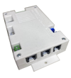
Dimensions
Length: 135mm (5.31") Width: 80mm (3.15") Maximum Height: 26.5mm (1.04")
Functions and Modes of Operation
Installs on your layout to provide direct Wi-Fi control and supply of Track DCC as well as Control Bus DCC to one or more DCC Boosters. It also provides bipolar DCC power to a Programming Track.
Provides two NCE Cab Bus connectors and acts as Cab Bus Master to communicate with connected devices using NCE Cab Bus protocol.
Output Ratings
Maximum Continuous Current Programming Track: 1.0 Amp.
Maximum Continuous Current Mai Track: 5.0 Amp.
Power Supply Options
(1) 12 to 18 Volts DC independent power, wired to screw teminals on unit. This unit does not operate using AC. Input must be connected with correct polarity
but module is protected against power reversal.
(2) Plug-in 15V mains adapter connected directly to unit at least 6 Amp recommended - available separately.
Mounting
Two M3 contersunk holes on base flanges to mount with wood screws. Two M3 holes in front flange with hex nut grips to mount from front.
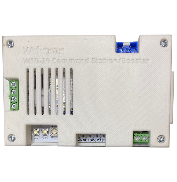
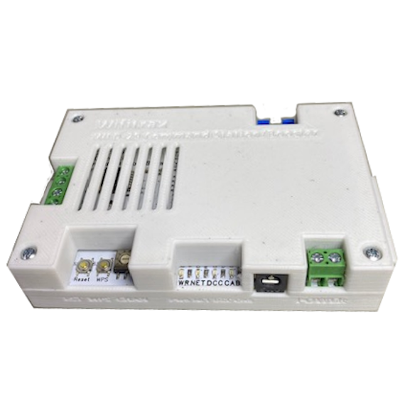
Connections
One RJ10 socket to be used as output for balanced RS-485 DCC Control Bus from Command Station to one or more DCC boosters.
Two RJ12 sockets to be used as NCE Cab Bus Connectors for 4-wire Cab Bus Cables. Supplies 12V power on each cab bus connector according to NCE Cab Bus specification.
One pair of screw terminal outputs to connect bipolar DCC power to programming track.
One pair of screw terminal outputs to connect bipolar DCC power to main track.
Two screw terminal connections for DC power input, (acts as power output when barrel connector used).
Barrel connector for alternative 15V DC Mains Adapter (Sold Separately).
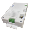
LED Indicators
Red LED indcates that power is present at the unit.
Green LED flashes when a hand-held device communicates via Wi-Fi, Slow flash for reset, quick flash for WPS.
Blue LED indicates DCC supplied to Control Bus.
Yellow LED indicates traffic on the NCE Cab Bus.
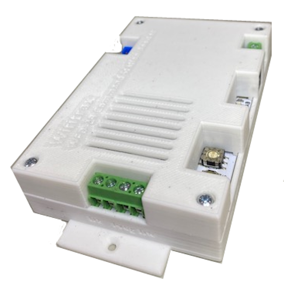
Controls
Wi-Fi Channel Selector rotary switch.
Reset push button.
WPS Button (Wi-Fi Protected Setup for easy connection to a home router).
Mains Adapter Details
The power adapter must supply between 12 and 18 Volts DC (15V recommended) with a Barrel Plug (2.5mm I.D. x 5.5mm O.D. x 9.5mm). The center pin must be positive. A recommended power adaptor is available from WifiTrax: http://www.wifitrax.com/products/product-PA15-43-1-detail.html
Protection
The output DCC driver to the main track is protected against shorts.
The output DCC driver to the programming track is protected against shorts.
Protection is provided against accidental reversal of the power input to the module.